| CHAPTER 1 THE BASIC TERMINOLOGY OF THE RELAYS
1. Contact Parameters
1.1 Contact forms are the arrangements of the relay contacts. The basic contact arrangement is shown in Table 2, the multi-contact arrangements can be ratiocinated.
1.2 Contact resistance is the total resistance between the contacts, the terminals and spring jointed with contacts, generally shown in m*.
Unless otherwise stated in the catalogue, generally for the relay with contact load below 2A, its contact resistance is measured in 6Vd.c., 0.1A; for the relay with contact load above 2A, its contact resistance is measured in 6Vd.c., 1A.
1.3 Contact voltage drop generally is, in the load circuit, the total voltage drop between contacts, springs jointed with contact and the terminals. It is generally described in the voltage drop value in the regulated current, for example 50mV (measured in 10A).
1.4 Contact material is the material used in contacts and generally shown in chemistry formula, for example, AgNi represents silver-nickel alloy contacts. The materials used in the relay, its characteristics and its application environment can be seen in 1.2 'Contact material' in chapter 2 'the principles for selecting relays'.
1.5 Contact rated load generally refers to the load which the contacts can switch reliably under the certain regulated conditions. Generally it is shown as the combination of the voltage and the current. The loads listed in the catalogue are resistive loads, unless otherwise stated.
1.6 Max. switching voltage is the maximum load voltage which the contacts can switch. In general application, this voltage value shall not be surpassed, or the relay endurance will be reduced.
1.7 Max. switching current is the maximum load current which relay contacts can switch. In general application, this voltage value shall not be surpassed, or the relay endurance will be reduced.
1.8 Max. switching power is the maximum load power which relay contacts can switch reliably. Generally for AC it is shown in VA while for DC it is shown in W.
1.9 Mechanical endurance refers to the operations that the relays without load or load which do not lead to failure under the rated voltage, normally switch in the specified, generally it is shown in operations.
1.10 Electrical endurance generally refers to the operations that the relay can normally switch when the specified load is applied on the contacts and the rated voltage is applied to the coil on the conditions that the relay is placed in the certain speculated environment. Generally it is shown in operations.
1.11 Surge current generally refers to the maximum transient current which the relay can endure in specified load.
1.12 Min. applicable load generally is the minimum load that the relay can switch reliably. According to ON-OFF frequency, environment and the difference of the required contact resistance, the reliability of Min. applicable load is different. Under the different conditions, the min. load to be switched is different.
2. Characteristics Parameters
2.1 Insulation resistance is the impedence when the conductors insulated with insulating material are applied to voltage and it is generally shown in "mΩ". The speculated voltage discribed above are generally 500Vd.c.(or 250 Vd.c.).
2.2 Dielectric strength is the voltage value when, within the speculated time, the conductors insulated with insulated material are applied to the voltage and the leakage current is less than the speculated current. The certain voltage above generally is the effective value of AC voltage and unless otherwise stated, the leakage current is generally less 1mA.
2.3 Operate time refers to, with the relay in the released state, the elapsed time from the initial application of power to the coil, till the closure of the normal open contacts. It does not include any bounce time, and expressed in "ms".
For the latching relays, operate time refers to, with the relay in the reset state, the elapsed time from the initial application of power to the coil, till the closure of the normal open contacts. Seen in figure 2.
2.4 Release time refers to, with the relay in the operation state, the elapsed time from the initial removal of coil power till the re-close of the normal closed contacts. It does not include bounce time and expressed in "ms". Seen in figure 2.
2.5 Reset time (only for the latching relays) refers to, with the relay in the operation state, the time from the first application of power to the reset coil till the re-close of the normally closed contacts. Seen in figure 2.
2.6 Bounce time generally refers to the time from the initial close of the contacts till the complete close and generally expressed in "ms". Seen in figure 2.
2.7 Switching frequency refers to the cycling times of the operation and release in united time.
2.8 Ambient temperature refers to the temperature in which the relay can normally be applied and it is generally expressed in the range of temperature.
2.9 Coil temperature rise refers to the temperature that the coil rises by after the temperature becomes stable and on the conditions that in the suitable maximum ambient environment the rated voltage is impressed on the coil and the rated load is impressed on the contacts. Generally it refers to the maximum value, expressed in K.
2.10 Shock is divided into shock functional and survival.
Shock functional refers to the acceleration the relay can suffer the shock value under the condition of the NC contact open time and open contact closing time at specified time. Usually it is expressed in the combination of the acceleration value "g" and the duration "ms".
Shock survival refers to the shock value that can not damage the relay construction, Usually it is expressed in the combination of the acceleration value "g" (1g=10m/s2) and the duration "ms".
2.11 Vibration resistance is divided into Vibration functional and survival.
Vibration functional refers to the vibration the relay can suffer without causing the closed contacts to open for more than the specified time and the open contacts to close for more than the specified time. It is usually expressed in the combination of the vibration "mm" and the vibration frequency "Hz".
Vibration survival refers to the vibration the relay can suffer without damaging their construction. It is usually expressed in the combination of the vibration "mm" and the vibration frequency "Hz".
2.12 Humidity refers to the required humidity in which the relay can normally work and generally expressed in relative humidity "RH%".
2.13 Model Of The Terminals
The terminals model of the relays also shows the applicable fields. Generally speaking, the models of terminals are PCB, THT, SMT, plug-in, QC and others.
2.14 Weight : the weight of the relay.
2.15 Enclosure type refers to the protection mode for the relay body. It is divided into enclosed, dust protected, flux proofed, wash tight and hermetically sealed. Seen in 3.1 'mode of encapsulation' in chapter 2 'the principles of selecting the relays'
3. Coil Parameters
3.1 The rated coil power refers to the power consumed by the coil when the coil are applied to the rated voltage. Generally for the DC relay, it is expressed in W while for the AC relay in VA.
3.2 Rated voltage is the voltage applied to the coil in order to make the relay work normally. It is expressed in "V". For the polarized relay, the direction in which the voltage is impressed should be notified.
3.3 Operate voltageis the voltage which closes the NO contacts when the relay is in the releasing state (for the latching relay in the reset state) and the coil voltage is increased gradually. Usually it is expressed in "V". It is usually the maximum value listed in the instructions, which is about 80% of rated voltage.
3.4 Release voltage is the voltage which closes the NC contacts when the relay is in the operate state and the coil voltage is gradually reduced from the rated voltage. It is usually expressed in "V". The minimum value is listed in the instructions, which is about 10% of the rated voltage.
3.5 Reset voltage is the voltage which closes the NC contacts when the latching relay is in the operate state and the reset coil voltage is increased. It is expressed in "V". The maximum value is listed in the catalogue, which is about 80% of the rated voltage.
3.6 Coil resistance generally refers to the DC resistance and is expressed in "*". In the catalogue the combination of the nominal value and tolerance is given.
3.7 Maximum allowable voltage refers to the maximum voltage which can be applied to the coil in the short time. It is expressed in V.
4. Safety Approval
4.1 UL Approval
UL, the abbreviation of Underwriter’Laboratories Inc, is non-profitable organization founded in 1984. The electricalproducts authorized by this organization can be freely sold in American market while The electrical products not authorized by this organization will be limited when they are sold in most of the stated in America. Duo to the authority of UL, the products approved by UL are accepted by many countries.
4.2 CSA Approval
CSA, the abbreviation of Canadian Standards Association, is the authorized approval institution. The electrical products approved by this institution can be freely sold in Canadian market. The products approved by the CSA can be only sold in Canadian market and if these products want to enter into the American market,theyshallget the American approval of UL.
4.3 UL&CUR
UL&CUR is the approval which simultaneously meets the American standard and the Canadianstandardand can be used in North America.
4.4 VDE Approval
VDE, the abbreviation of Verband Deutscher Elektrotechniker, is one of Germanyauthorizedorganizations in electrical component and other equipment. The electric products approved by this institution will be admitted in Germany law.
4.5 TüV Approval
TüV, the abbreviation of Technischer überwachungsverein, has the same authority as VDE.TüV is one of the authorized institution in electric equipments.The electric products approved by this institution will be admitted in Germany law.
4.6 CQC Approval
CQC, the abbreviation of China Quality Certification, is the most authorized approval institution in China.The products not listed in the catalogue of3C approval can make CQC approval inChinaQualityCertificationCenter.
5. Ordering Code
Ordering code is a code which is used to ensure the type and the specifications of the relay, which includes the basic information of the relays, such as the type of the products, the coil voltage, contacts arrangement, the enclosure type etc.. The ordering code of GEO brand relay can be seen in Chapter 5 "the ordering code".
6. Outline Dimensions, Wiring Diagram And The Size Drawing OfThe Mounting Holes
Ordering mark is a mark which is used to ensure the type and the specifications of the relay, which includes the basic information of the relays, such as the type of the products, the coil voltage, contacts arrangement, the mode of encapsulation etc.. The ordering marks of GEO brand relay can be seen in Chapter 5 "the ordering marks".
6.1 Outline dimensions describes the drawing of the relay outline size and the mounting space needed by relay.
6.2 Wiring diagram describes the wiring way of the input and output terminals respondent to the terminals of the relays.
6.3 The size drawing of the mounting holes describes the position of the relay terminals and the size of their mounting holes.
6.4 Examples
The examples of the common components can be seen in table 3.
7. Characteristic Curves
7.1 Max. switching power curves represent the loads the relay can support.
7.2 Electrical endurance curve shows the life of the relay in all kinds of loads.
7.3 Coil temperature rise curve shows the measured temperature rise value of the coil when the relay is energized with different voltage and loads under the speculated ambient temperature.
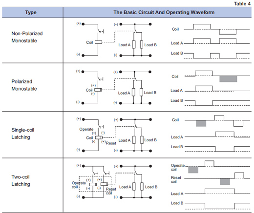
8. Monostable, Latching And Polarized Relays
8.1 Monostable Relay : For this relay, the contacts operate when the coil is energized while the contacts will reset when the coil is deenergized.
8.2 Latching Relay : For this relay, the contacts operate when the coil is energized while the contacts will keep the state when the coil is deenergized. To reset the contacts, the counter-energization will be applied to the single-coil coil or the energization is applied to the double-coil reset coil .
8.3 Polarized Relay : The switch of the contact state is dependent on the polarity of the energized voltage in the terminals of the coil. Part of the monostable relays and all the magnetic latching relays belong to polarized relays.
The basic circuit and operating wave of the several common relays can be seen in table 4.
|