| CHAPTER 2 THE PRINCIPLES OF SELECTING THE RELAYS
In order to correctly select relays, the customers need know about the characteristics of the relays to ensure whether these characteristics meet with the practical requirements. It will be more reliable if these characteristics can be tested in the practical environment. The principles of selecting the relays can be seen in table 5. In table 5,in the column "must be confirmed" the item with the mark * is confirmed and a type of relay can be selected. If there is further requirement, the correspondent items with the mark * are required to be further confirmed.
Table 5
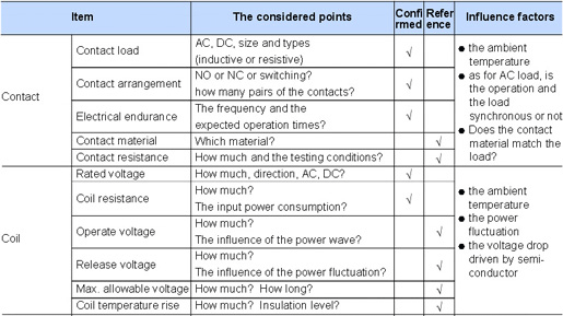
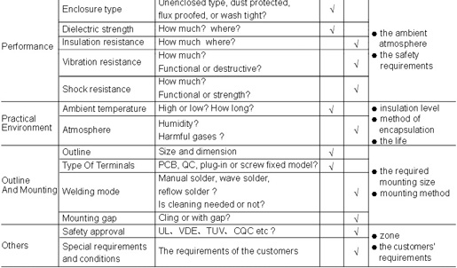
1. Contact Parameters
1.1 Contact Load
Before ensuring whether the load the relay can carry in order to meet with the application, we should confirm the type of the real load except for confirming the load value for different loads have different steady state value and inrush value. Seen in table 6. The load given in the instructions generally are the resistive load, unless otherwise stated.
Table 6
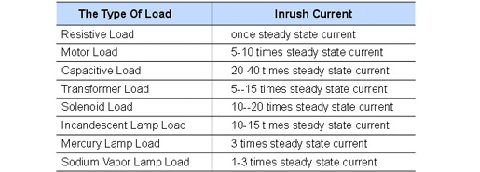
Figure 3 shows the relations between the representative load and the inrush current. In addition, according to the characteristics that the polarity of different moving and stationary contacts will influence the electrical endurance. Please check in the practical application or consult the technician in Pinso company.
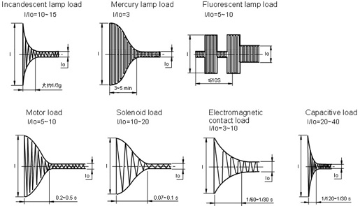
Figure 3
1.2 Contact Material
For the same type of relay, the different contact material is applicable to different load types or ranges. Seen in table 7.
Table 7
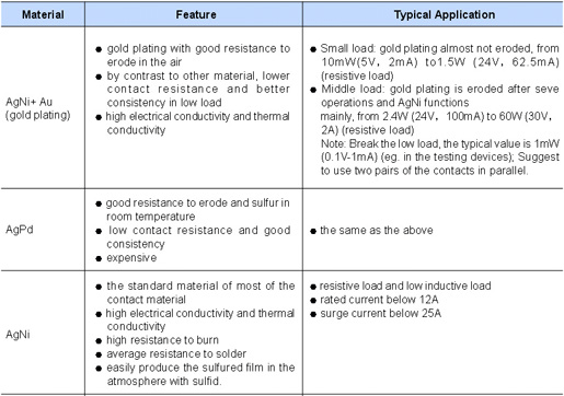
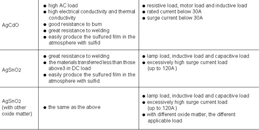
Notes:
1) Consider the maximun current value specified in different relays.
2) It would better be checked and rested in application when the conditions are catlogue allowable . Gold plating of the contacts shows good performance for thelow loads . However , for the high load , it canonly keep the initial contact performance of the contacts before the relays are used .
1.3 Electrical Endurance
Unless otherwise stated, electrical endurance listed in the catalogue is the nominal value in the rated load, the certain temperature, load and operation frequency. Therefore for other types of load and switching frequency, electrical endurance is different.
For the load above 2A and for the same mode relays electrical endurance of the flux proof type and the dust protective type is longer than that of the plastic sealed type. Therefore in the conditions allowable, to the extent that it is possible, The relays of the flux proof type and of the dust protective type are used to increase the life of the relays.
2. Coil
2.1 Voltage
To make the relay work reliably, be sure that work circuit can supply the rated voltage to the coil.
Sometimes to shorten the operating time, the coil can be applied to maximum allowable voltage to the coil in the short time. However it should be ensured that the relay will not overheat or even be damaged.
For polarized relays, please check the polarity of the coil voltage.
2.2 Coil Resistance
To make the relay work reliably, be sure that work circuit supplies the nominal coil power consumption to the relay. Therefore please select the suitable coil resistance
3. Performances
3.1 Enclosure Type
To ensure the reliability of the relay, different ways of encapsulation will require different post-processing(table 8).
Table 8
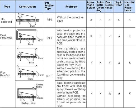
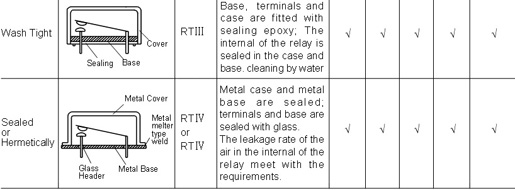
3.2 Dielectric Strength And Insulation Resistance
Please confirm that these two parameters can meet the application requirement and will not lead to such conditions as the breakdown of the circuit, short circuit.
3.3 Vibration Resistance And Shock Resistance
Please confirm that these two parameters can meet the application requirement and will not lead to the failure of the relay in the course of the application.
4. Temperature
4.1 Ambient Temperature
Generally speaking, when the temperature does not exceed beyond temperature range speculated in the catalogue, the relay can normally work. When the temperature in application is higher than the temperature speculated in the instructions, please contact Pinso to ensure whether the relay can be normally used according to the loads.
4.2 Atmosphere
In the atmosphere with high humidity, even freezing dew and much dust, recommend to use sealed relays for the high humidity easily accelerates the rust of the relay parts and the dust easily result in the failure of the relay contacts.
In the atmosphere with organic silicon, recommend to use hermetic products for the organic silicon will accelerate the failure of the contacts. In the atmosphere with such harmful gases as H2S、SO2、NO2etc., the flux proofed and dust protected products can not be applied while the wash tight products can be used and tested in application.
In application, if the ambient atmosphere is better, recommend to use the dust protected and flux proofed relays for they can get the longer eletric endurance than wash tight relays.
5. Outline And Mounting
5.1 Outline And Mounting Gap
The outline sizes of the relays usually have a certain tolerance. Therefore when the circuit and the mounting gap are designed, the design is suggested to be done according to the maximum size in the instructions.
5.2 Welding Methods
Since July 1st, 2006, the terminals of the relays produced have been lead-free. The suggested welding temperature and time are respectively 240℃ to 260℃, 2s to 5s.
If reflow solder is required, it shall be confirmed the relay canbe reflow soldered according to the instructions. If you have questions, please contact Pinso.
5.3 The Model Of The Terminals
Select the suitable shapes of the terminals and mounting methods according to the real conditions.
Table 9

Table 10
6. Others
6.1 Safety Approval
Generally UL&CUR approvals are applicable in North America and VDE&TüV approvals are applicable in European. However, due to the international authority of these approvals, most of other countries also accept them. If you have questions, please contact Pinso.
6.2 Special Requirements
Except for normal products, we accept the customer’s order for the products with special specifications
Please contact Pinso where required.
|
